 |
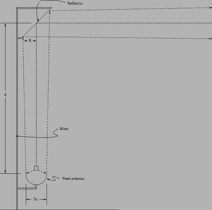
The purpose of the Periscope Antenna is to achieve the beneficial effects of height with out having to either put the transceiver up a mast or run long lengths of expensive coaxial line. This is attained by placing the driven element on, or near the ground, and a reflector at the top of the mast. A schematic of the arrangement is shown in figure 1.
Interestingly, the combination of a feed antenna and reflector can provide significant gain over that of the feed antenna alone.
The independent variables are
![]() and
and ![]() , where
, where ![]() is the transmission wave length (approx. 12cm for IEEE 802.11b) and the other variables appear in Figure 1.
This gain increase peaks at values of
is the transmission wave length (approx. 12cm for IEEE 802.11b) and the other variables appear in Figure 1.
This gain increase peaks at values of
![]() between about 0.25 and 0.5.
The gain increase is maximized as
between about 0.25 and 0.5.
The gain increase is maximized as ![]() trends to zero - that is as the feed antenna approaches a point source.
Magnitudes of gain increase of between 4dB and 6dB can be achieved.
trends to zero - that is as the feed antenna approaches a point source.
Magnitudes of gain increase of between 4dB and 6dB can be achieved.
Antennae of this type were once common in the US where they formed the back bone of the telecommunications system. Now that this industry is moving from RF to coaxial and fiber mediums they are seen less frequently. I have never seen them in this country (Australia).
The telecommunications industry typically operates their links around the X band (or above).
This tends to reduce the necessary size of ![]() for a given
for a given ![]() and gain increase.
In the IEEE 802.11 context, where most link frequencies are near 2.4GHz, this sort of antenna may become unwieldy as
and gain increase.
In the IEEE 802.11 context, where most link frequencies are near 2.4GHz, this sort of antenna may become unwieldy as ![]() increases because
increases because ![]() has to increase also (although note the square root).
Therefore, antenna height becomes a problem at these lower frequencies.
If height is required it may be necessary to reduce
has to increase also (although note the square root).
Therefore, antenna height becomes a problem at these lower frequencies.
If height is required it may be necessary to reduce ![]() .
Obviously, this may be done by mounting the feed antenna some way up the mast.
.
Obviously, this may be done by mounting the feed antenna some way up the mast.
Because of the narrow beam widths that are usually involved it is necessary that this type of antenna have a certain mechanical stiffness both in terms of the relationship between the feed antenna and the reflector, and in the sense of the reflector azimuth etc.
Another possible use for this arrangement may be to use the reflector to modify the beam pattern. For instance, it may be possible to convert the narrow beam pattern of the feed antenna to a omni directional pattern by using a suitably shaped reflector.
There is an excellent discussion of Periscope Antennas in Chapter 8 of the W1GHZ Online Microwave Antenna Book.
$Id: periscope.tex,v 1.2 2002/11/28 16:12:33 pfb Rel $